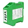
| ALARM VSC-AL | ||||||||||||||||||||||||||||||||||||||||||||||
FeatureThe alarm of set point is output to an incoming signalRotary switch set point adjustments. Alarm output is possible for no-voltage contact Selection with an internal switch is possible for input and output specification (0 to 1mA, 4 to 20mA/ make contact , break contact ) |
 |
|||||||||||||||||||||||||||||||||||||||||||||
Specification
|
||||||||||||||||||||||||||||||||||||||||||||||
Notes1.EnvironmentBe careful not to close the slit for thermal radiation Avoid areas that are direct sunlight, dust, or receives radiation of heat from other. Avoid areas that are corrosivity gas, flammable gas, libration and force. Avoid areas that are large noise serge. 2.Precautions However [power supply-input signal] of main product is not insulated, mature consideration at the time of the design of a control device. Please attach a serge measure component in the side of output circuit, so that noise serge is not impressed to output terminal. 3.The stop on operation Carry out conduct electricity inspection of an output point of contact periodically. Since it is tended to generate a point of contact an insulation film when using it especially by minute load, cautions are required. Be careful OUT L-OUT H may be outputted in instant, conducted electricity to main product when a setup of HIGH-LOW is changed. A power supply is shut off, and be sure to perform a setup of SW7, SW8, and SW9. Use a minus driver with a tip width of 2.5mm or less for operation of the vertical setup SW. |
||||||||||||||||||||||||||||||||||||||||||||||
Technical DataSetting value selection table
Attachment Method 1.How to OPEN  2.The position of SW  The specification of output can be set up by DIP SW 1-2. The kind of input signal can be set up by DIP SW 7-8-9. Input selection table
Output selection table
Front panel configuration  |
||||||||||||||||||||||||||||||||||||||||||||||
Wiring, Block diagram
|
||||||||||||||||||||||||||||||||||||||||||||||