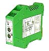
| SPLIT-RANGE TRANSMITTER VSC-SP |
|
|
|
|
Feature
Split range control uses two sets of different control valves.
A set up of the translating to change to V, is easy
V-control characteristic
 |
Proportional characteristic
 |
 |
|
Specification
| Specification |
4 to 20mA signal Split range transmitter |
| Classification |
VSC-SP |
| Voltage |
DC24V ±10% |
| Power required |
2W MAX. |
| Input signal |
4 to 20mA (Input resistance 250ohm.) |
| Output signal |
4 to 20mA 2 (Proportional control side: input resistance 600ohm. less than) |
| Resolution |
Less than 0.2% |
| Response time |
1sec.less than (Input signal 0 to 100%) |
| Temperature Characteristic |
Less than 5μA/°C |
| Ambient temperature range |
-10 to 50°C |
| Ambient humidity range |
30 to 85% Non-condensation |
| Terminal board |
For naked wires Conformity wire
0.2 to 2.5mm² (AWG24 to 12) |
| Attachment method |
DIN rail attachment (35mm) |
| Outside dimension |
W 23 , D 115 , H 99 (mm) (DIN rail from an attachment side) |
| Special AC power supply unit is prepared. Please consult us. |
|
|
The example of use
| V control characteristic |
 |
| Proportional characteristic |
 |
|
|
Notes
1.Environment
Be careful not to close the slit for thermal radiation.
Avoid areas that are direct sunlight, dust, or receives radiation of heat
from other.
Avoid areas that are corrosivity gas, flammable gas, libration and force
Avoid areas that are large noise serge.
2.Precautions
However [power supply-input signal-OUT A OUT B ] of main product is not insulated,
mature consideration at the time of the design of a control device.
In case of an actuator power supply is DC24V, please design a control device
according to the following clause.
Make sure separate the power supply of an actuator, and the power supply
of main machine and a regulation meter, or carry out isolation of the incoming
signal.
[OUT A ][OUT B ]make each actuator power supply separate, or carry out
isolation of the signal line.
The output which is not used should short circuit + and -.
|
|
Technical Data
Output selection table
| SEL A |
OUT A |
SEL A |
OUT B |
| Proportional characteristic |
V control characteristic |
| 0 |
10.0mA |
 |
0 |
6.5mA |
 |
 |
| 1 |
10.5mA |
1 |
7.0mA |
| 2 |
11.0mA |
2 |
7.5mA |
| 3 |
11.5mA |
3 |
8.0mA |
| 4 |
12.0mA |
4 |
8.5mA |
| 5 |
12.5mA |
5 |
9.0mA |
| 6 |
13.0mA |
6 |
9.5mA |
| 7 |
13.5mA |
7 |
10.0mA |
| 8 |
14.0mA |
8 |
10.5mA |
| 9 |
14.5mA |
9 |
11.0mA |
| A |
15.0mA |
A |
11.5mA |
| B |
15.5mA |
B |
12.0mA |
| C |
16.0mA |
C |
12.5mA |
| D |
16.5mA |
D |
13.0mA |
| E |
17.0mA |
E |
13.5mA |
| F |
17.5mA |
F |
14.0mA |
SW3
OUT B Proportional characteristic
 |
OUT B V characteristic
 |
Attachment Method
1.How to OPEN
 Both sides of a portion pushed in one side at a time using by a minus driver. Both sides of a portion pushed in one side at a time using by a minus driver.
 Upper part is pulled out about 4cm. Upper part is pulled out about 4cm.
2.The position of SW
The characteristic of OUT B is set up by SW3.
Front panel configuration
 |
|